


Troubleshooting
Auger Continuously Turning
Check encoder gears, voltage between the common signal wires (Black & White wires), and encoder cable connections or broken wires. If you do have any of these issues you can place the filler into time mode and run this way until the replacement parts are received. When running in time 1 second is equal to 10 turns. For example, if you are running 5 turns this would be .5 seconds.
Self-Feed products dripping
The auger may be set too high from the lip of the funnel or you may need a drip washer.
Free-Flow Products Jamming
Spinner Plate may be up too close to the funnel. Adjust the auger shaft in the hopper.
Clutch Brake
With the power on, there should be 90VDC between the common and the clutch brake. The red light should be lit on the Warner Clutch Brake power supply. When the Clutch is engaged the green light will be lit.
Fill Motor or Agitation Motor Not Running
Check Motor Overloads, they may have tripped due to some sort of motor AMP overload. Potential causes: 1. Product jam 2. Loose wires 3. Incorrect voltage 4. Overload set too low
Electrical Installation
Receiving Machine
Upon receiving your filling machine, please inspect the shipping crate for any damage that may have occurred in transit. Please report any damage to the transportation carrier in writing describing the damage. Please ensure to notify Image Fillers, Inc. regarding the damage. Note: ICC regulations stipulate that a damage claim must be submitted within seven (7) days of receipt. All machinery and parts come with a packing list, please check to see receipt of all items listed on the packing list. The Image Filler Inc. filling machine comes with all the major components pre-assembled and tested. These items include augers, funnels, blades, etc. that have been ordered specifically for your machine. These separate accessories also have a packing list and are to be installed by the user.
Site Requirements
Prior to installation, an area must be selected that meets all the necessary electrical, pneumatic and product supply requirements of your filling machine. (See specific layout for your filling machine) Careful and proper installation of your Image Fillers Inc. filling machine will result in accurate filling production, lower maintenance, and reduced risk of machinery failure.
Positioning of the Machine
The filling machine should be placed on a stable and level surface that includes the necessary electrical, pneumatic and product supply requirements. The filling machine needs to be placed in the upright operating position using a forklift or a power assisted machine. Use caution and avoid damaging the machine while moving it into the proper place and position. Once in place and level as required, secure to the floor using lag bolts, leveling pads are included. If the machine is equipped with casters, please make sure to lock the casters into place to avoid unnecessary movement. Inspect to all bolts and screws that may have become loose in transit.
Electrical Connections
Once the filling machine is properly positioned and secure, the electrical service at the site can be connected. All electrical installation should be completed by a qualified person and in accordance with all local codes and requirements. The specific electrical connections are shown on the wiring diagram that is supplied with your filler. The electrical specifications are also located on your machine. Use this information to correctly connect electrical service to your filling machine. The Image Fillers Inc. filling machine has motor starter equipment for proper and safe operation. The filling machine controls may also require a source of AC electrical power and may also require a source of AC electrical power as well as a separate transformer. If this equipment is not supplied with the machine, then install it at this time Refer to the wiring diagram for proper connection information for this machine.
Pneumatic Requirements
Some filling machines include pneumatic operated components such as lifts, indexing, clamping, cutoff, etc. If your filler has a pneumatic component, then your installation site should have an adequate source of clean, dry compressed air for connection to the regulator that is included with the filling machine. Recommended pressure and capacity ranges for compressed air operated filling machines are listed below.
Pneumatic Pressure Recommendations:
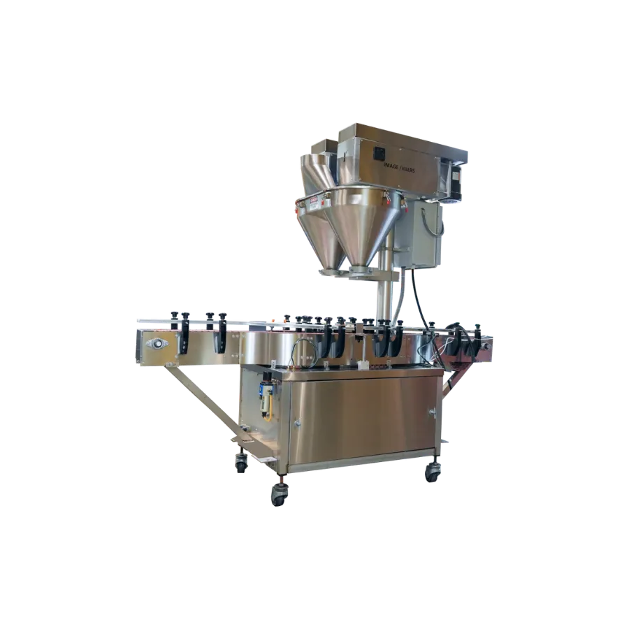
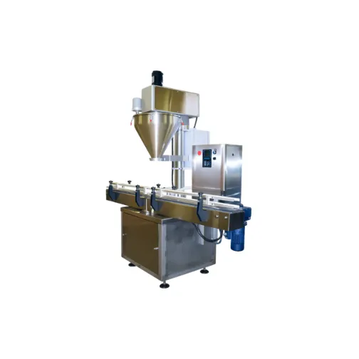
Single Head Automatic with lift and indexing (SCFM 7-8) (PSI 80)
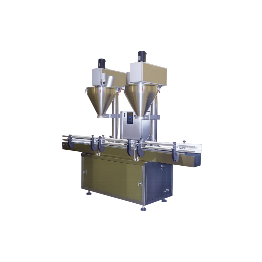
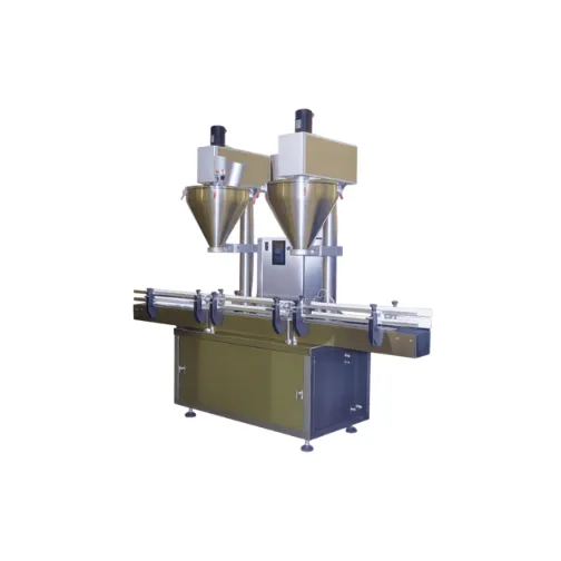
Dual Head Automatic with lift and indexing (SCFM 10) (PSI 80)
Product Supply
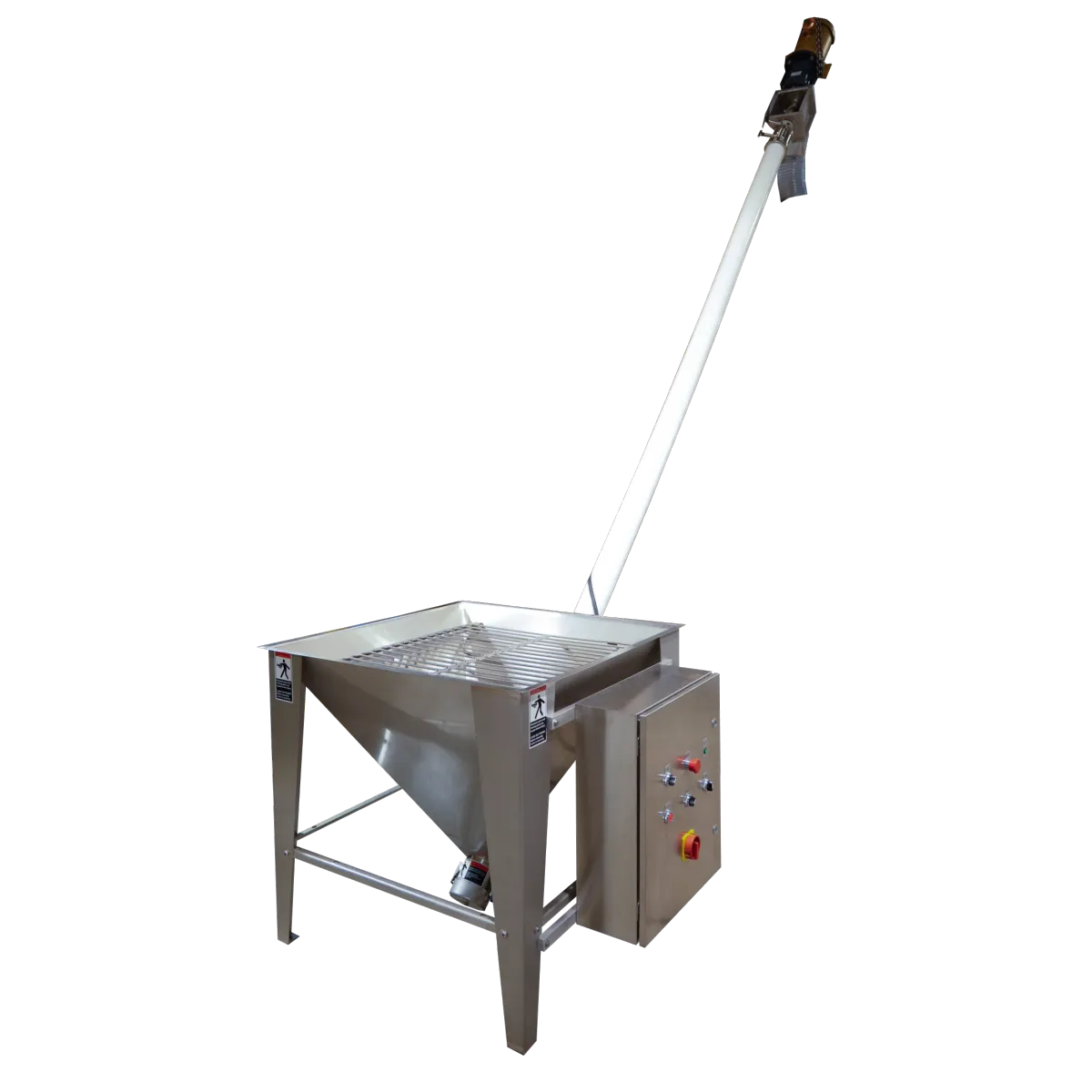
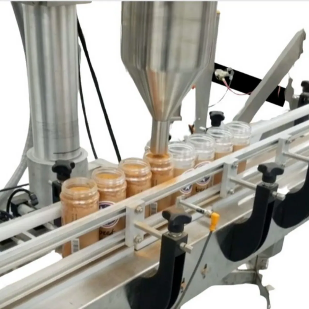
A consistent and reliable source of product is crucial for accuracy and overall operation of the filler. The product should be supplied within 2”-3” of the hopper to maintain proper pressure. The product may be either flood fed into the hopper or periodically resupplied by means of bulk type filler.
Motor Shaft Rotation
Once the electrical installation and connection are complete, power can be turned on. It is necessary to verify proper motor rotation as well as to select the correct auger rotation. The auger motor and slow speed agitation blade must rotate in a specific direction for proper filling. Rotation is selected by the 3-phase electrical power connections. These two motors should operate in the following direction. Filler Drive Motor should move counterclockwise Agitator Drive Motor should move clockwise Refer to illustration (A00770A) for motor rotation directions: If your machine is not connected correctly, then 1-disconnect all electrical power,2- switch any two connections from 3-phase power to the selected motor, and then- reconnect the electrical power. Dangerous voltages are present at these connections. Please ensure that all electrical power is disconnected and the safety disconnect switch is locked on an OFF position prior to changing these connections.

Basic Adjustments
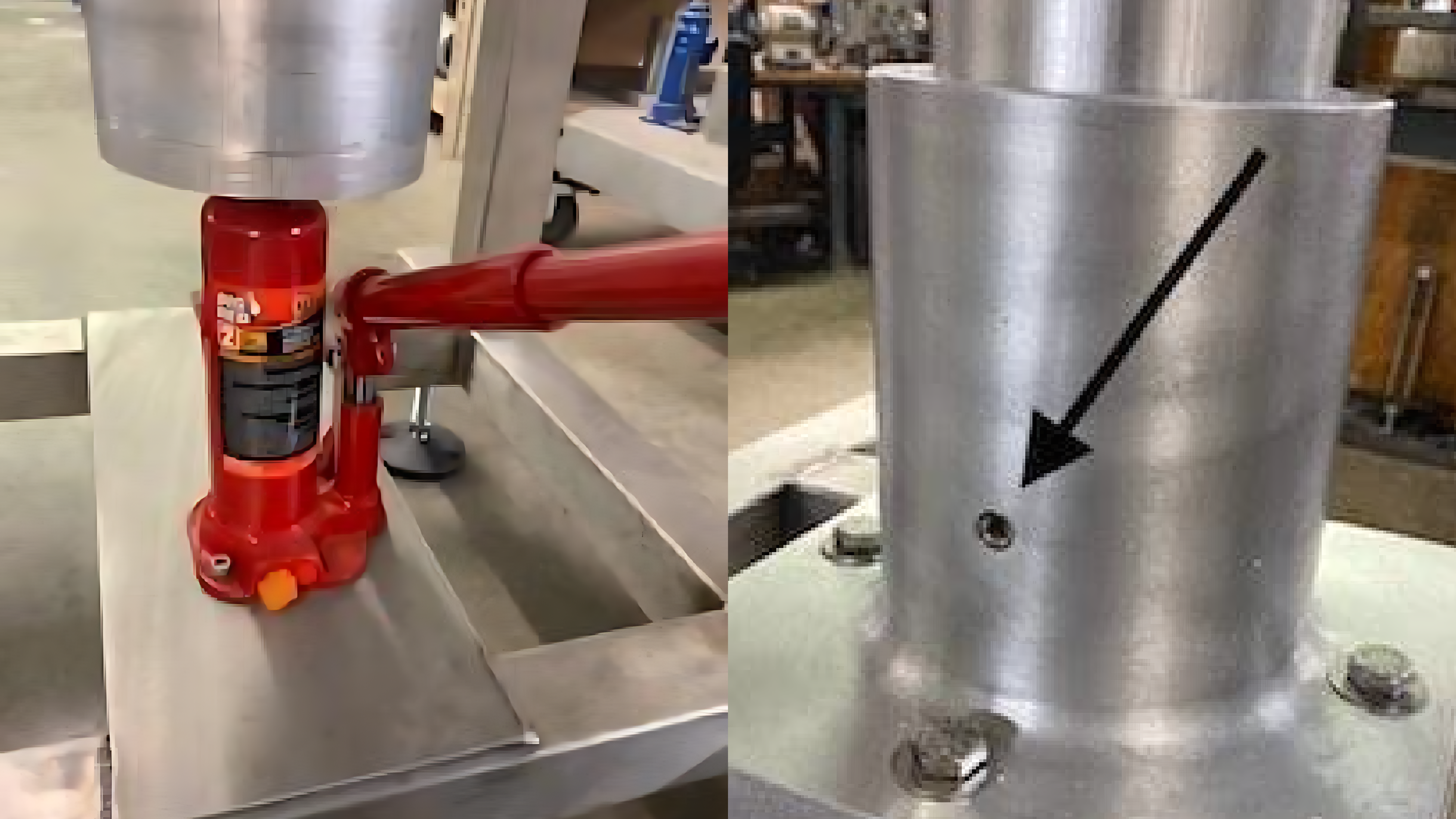
Jack Adjustment
The jack is typically used to adjust for the various size containers to be filled. The set screw (shown above in the bottom picture) needs to be loosened prior to adjusting the lift.
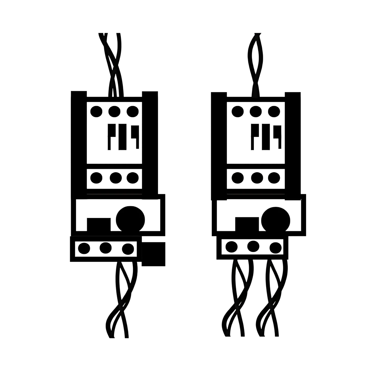
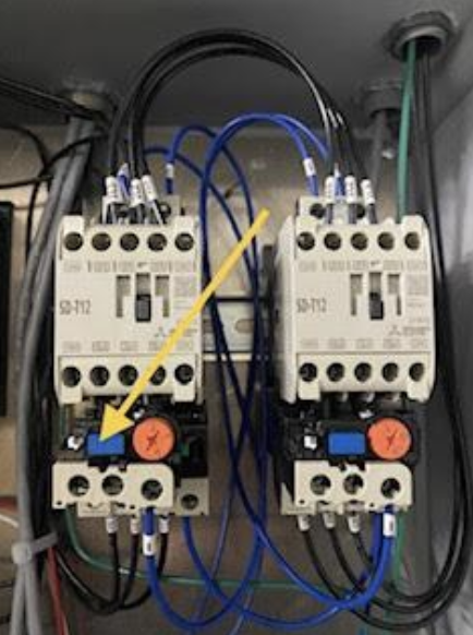
Contactors and Overloads
The contactor initiates then the motor will start to turn and the overload protects the motor. If the motor gets jammed, the overload will stop it. The orange adjustable dial is set for the amp load of the motor. The blue button (shown with the yellow arrow) is the reset button and can restart operation.
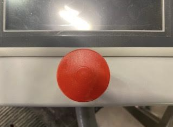
Emergency Stop
The E-stop should be left on the on position and only used for an emergency with the machine. Press the E-Stop to automatically stop the machine. Pull the E-Stop out when you wish to run the machine.
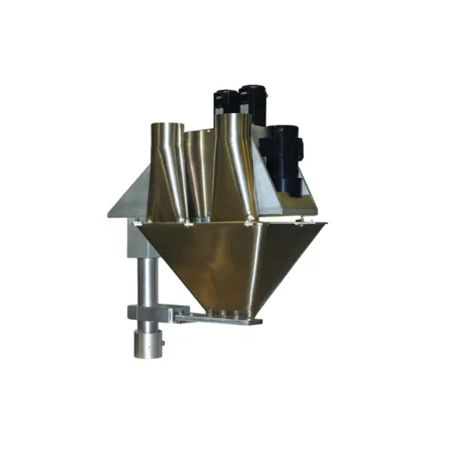
Types of Tooling
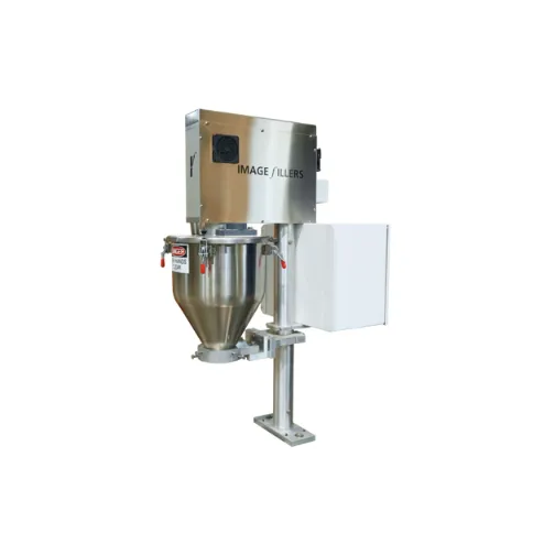
Non-Free-Flowing Powders & Granular Products
Liquids, Pastes, and Creams
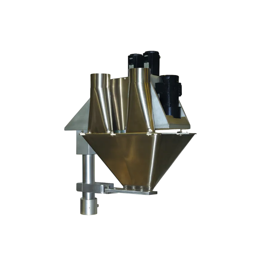
Free Flowing Powders & Granular Products

Hopper Alignment
The hopper must be aligned with the auger shaft. Misalignment can cause excessive wear and damage to the filling machine and the accessories. Your filling machine was aligned at the factory, but it should be checked and re-aligned if needed. Use the instructions shown in the following illustration. **** Alignment tool can be purchased separately****

Accessory Installation
Accessories are packed separately from the filling machine and must be installed by the user. Please refer to the diagram. Free Flow, Non-Free Flow, and Pump setups are as follows
1) Non-Free Flow Setup
The jack is typically used to adjust for the various size containers to be filled. The set screw (shown above in the bottom picture) needs to be loosened prior to adjusting the lift.
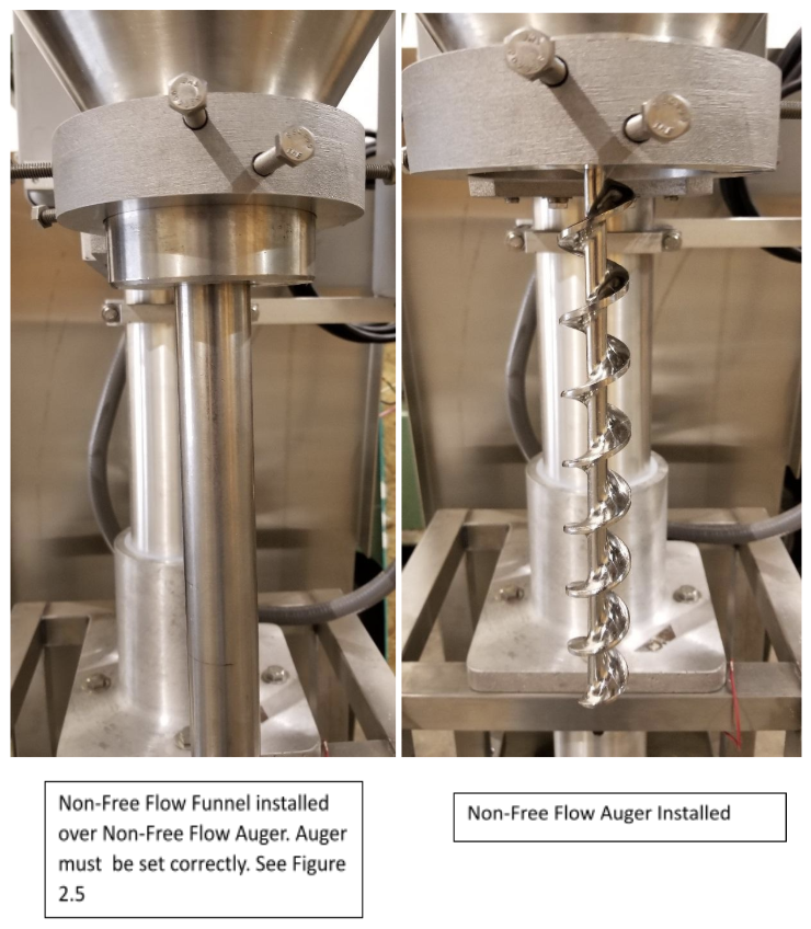
2) Non-Free Flow Setup
Auger should be ⅛”-1/16” away from the lip. The photo above illustrates the correct distance.
The installed drip washer helps with any product dripping issues.

Free Flow Setup
Click photo to see how the spinner plate is adjusted.

1) Removing the Hopper
Make sure to disconnect all power If the auger and or funnel are installed, you will need to remove the tooling. Click photo for more info.

2) Removing the Hopper
Be sure to place the Auger & Funnel in a safe place. Unlatch the 4 Destaco Clamps around the hopper. While supporting the hopper at the bottom of the coupling, loosen the 3/8-16 hex head bolt using a 9/16 wrench in the center of the hopper support. Do not loosen or remove the two 5/16-18 hex head bolts in the quick disconnect bracket and hopper and funnel coupling.

3) Removing the Hopper
The Hopper, Coupling & “L” Bracket will come off all together. If you loosen the two 5/16-18 Bolts you will lose the alignment.

Auger & Funnel Installation
Disconnect all electrical power at the safety disconnect. Lock in the “OFF” position to avoid injury or damage to the machinery. The auger is installed into a bayonet fitting in the auger shaft. Insert the pinned end of the auger into the recess and turn clockwise to lock in place.

Agitator Installation
When installing the slow speed blade, ensure to disconnect the electrical power. Optional Accessories- The high-speed agitators are secured to the Auger and/or Pump Shaft with a supplied hex head bolt through the blade collar

Common Terms
Agitation- The stirring action of a product in the hopper.
Agitation Blade- turns inside the hopper towards the auger and keeps the auger filled with product.
Auger- Screw shaped device that dispenses the product out of the funnel.
Clutch Brake- The clutch and brake motor drives the turns of the auger.
Counter- the part that counts the number of fill quantity/fill counts.
Fill Quantity- The setting that lets you know that amount of product being dispensed.
Funnel- A separate piece that attaches to the bottom of the hopper. Augers and Funnels size are based to match the product you are using.
Free Flow- This tooling type has a straight auger for the free flow products such as powders and sugar.
Hopper- The vessel that holds the material that is being packed and supplies the product to the tooling.
Indexing- the movement of containers along the conveyor through different stages. Index cylinders need air and electric power.
Level Control- the sensor that is used to control the level of product in the hopper.
Self Feed- This tooling type is used for powder products that require compression.
Tooling- The changable components of the filling machine to fill your product such as augers, funnels, collector funnels, etc.
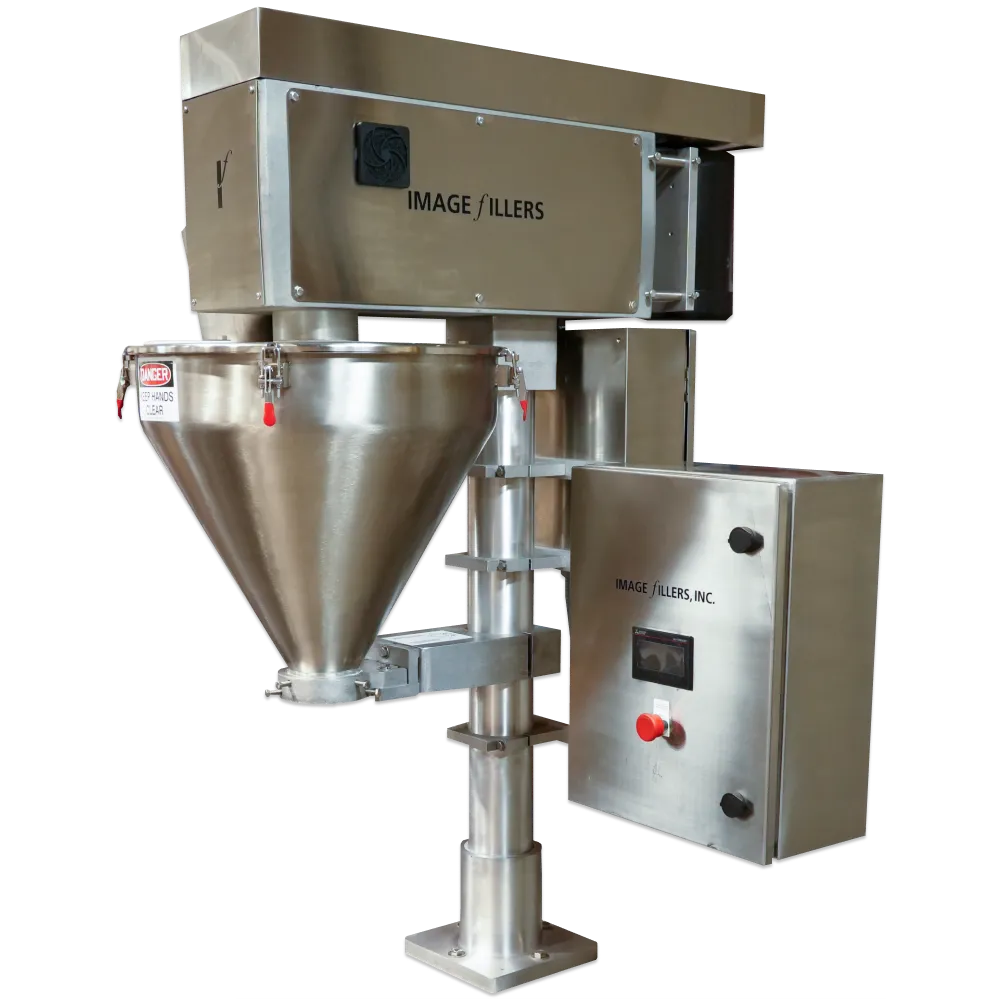
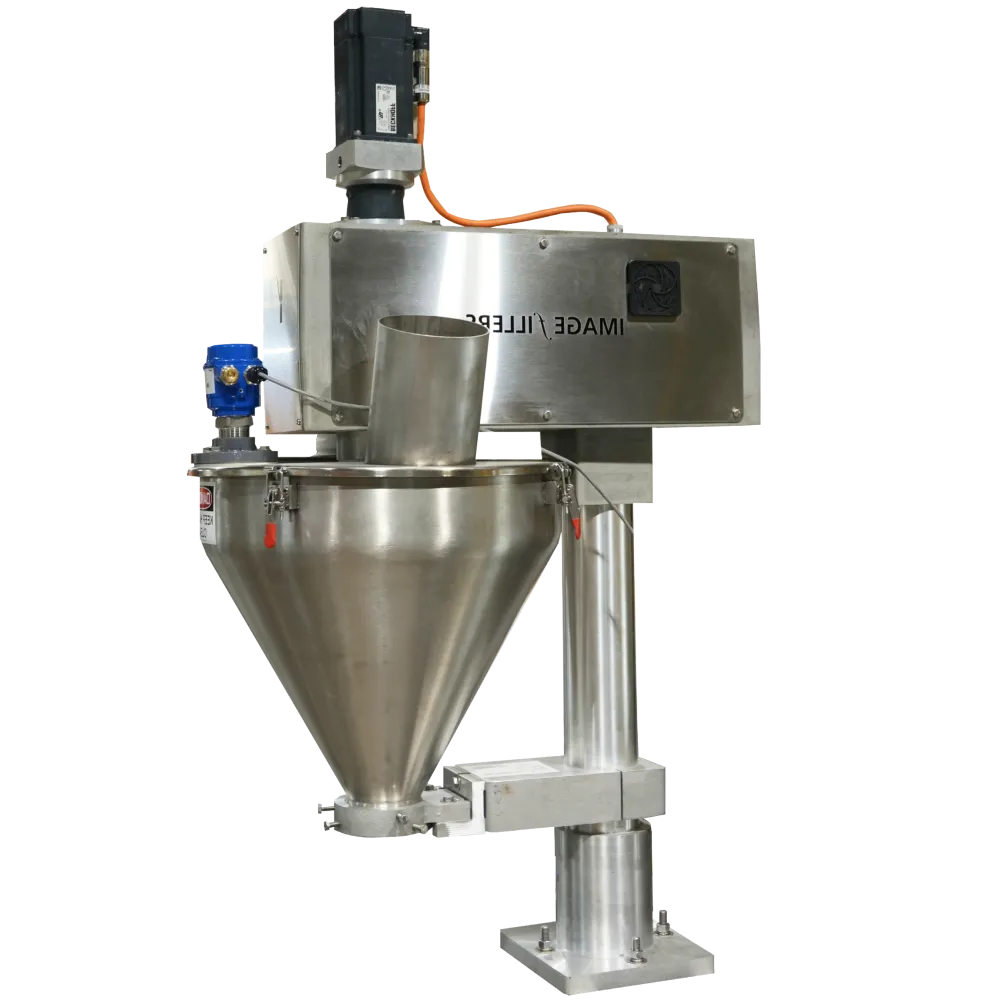
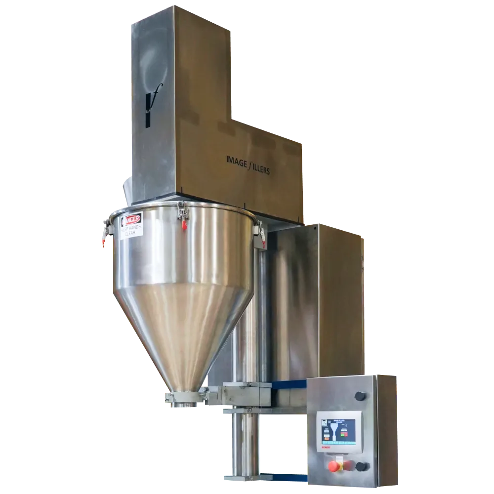
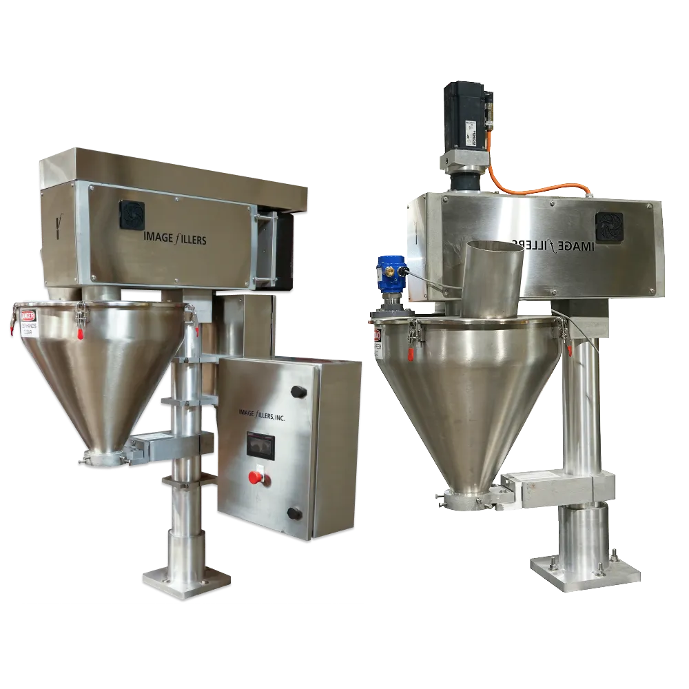
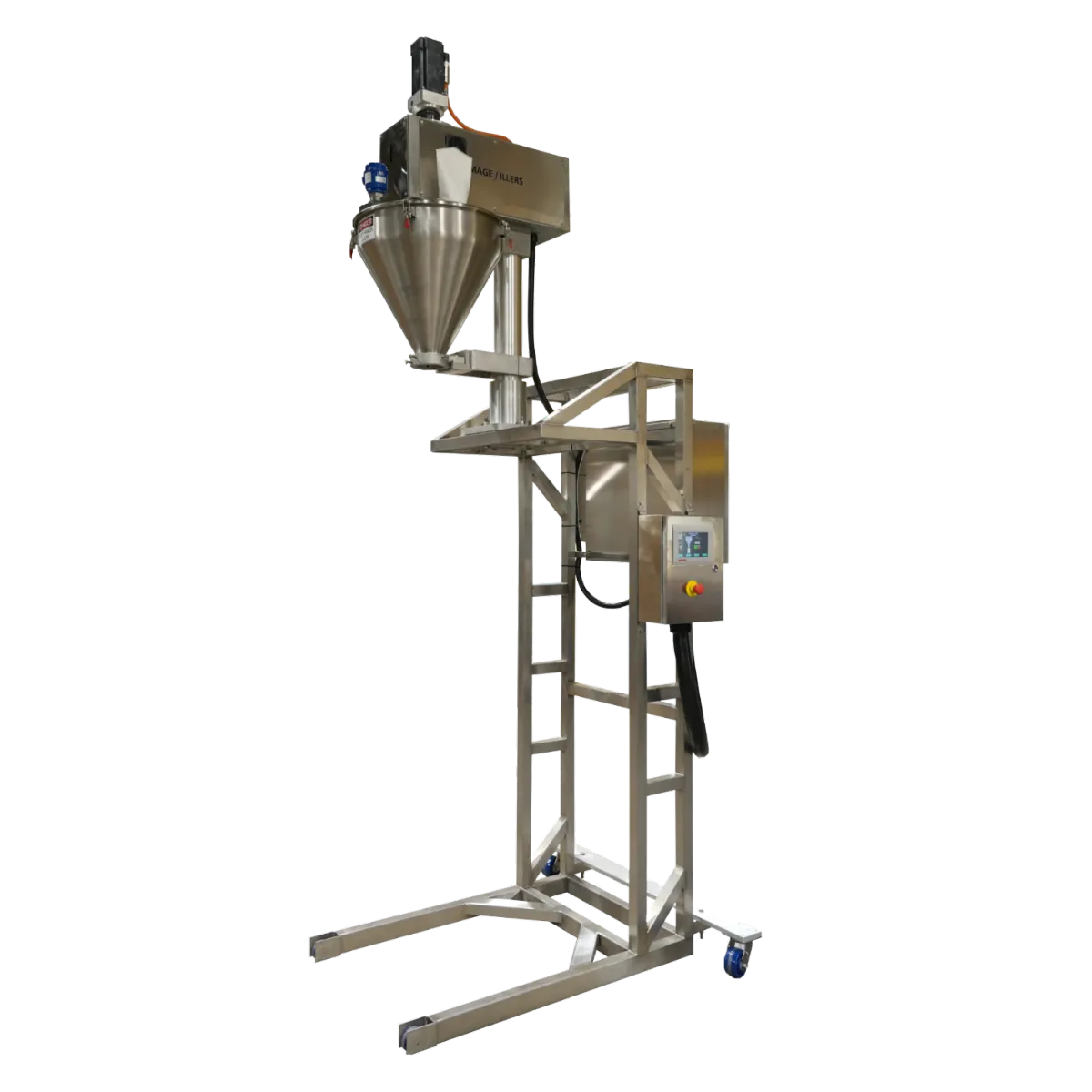
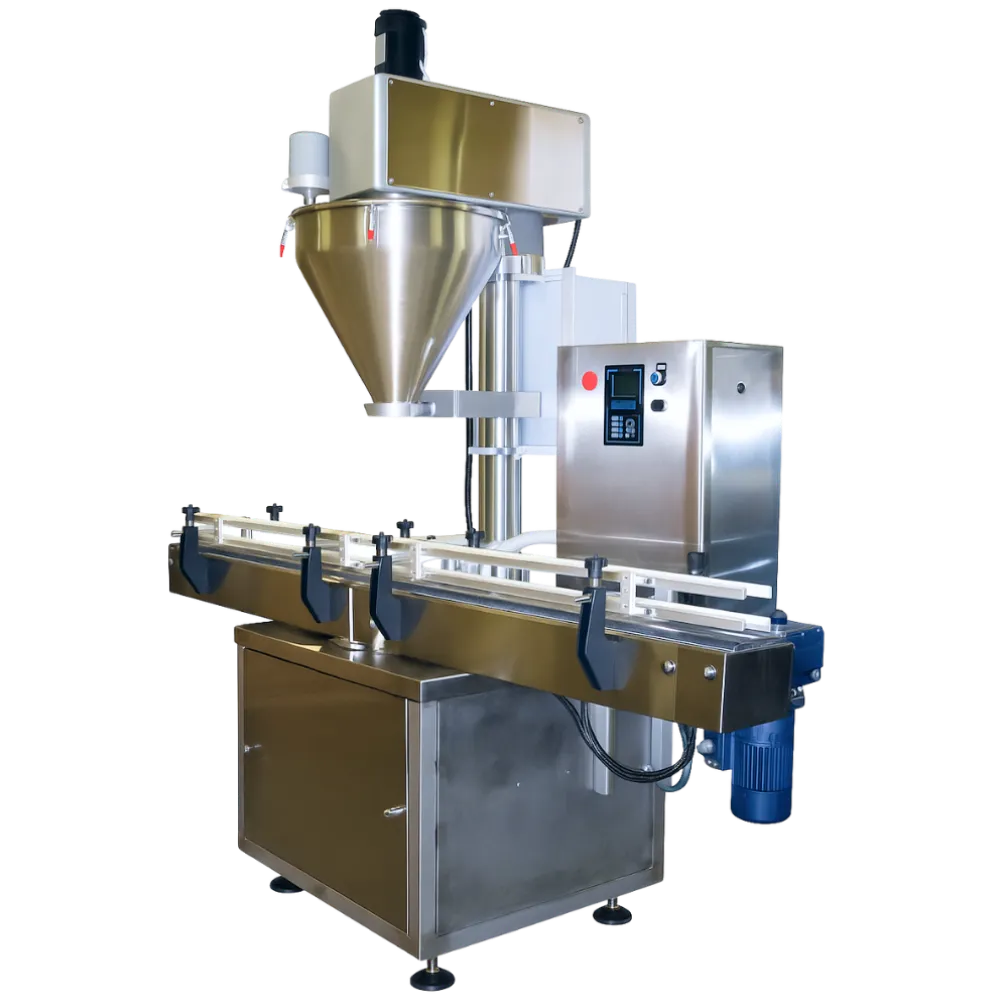
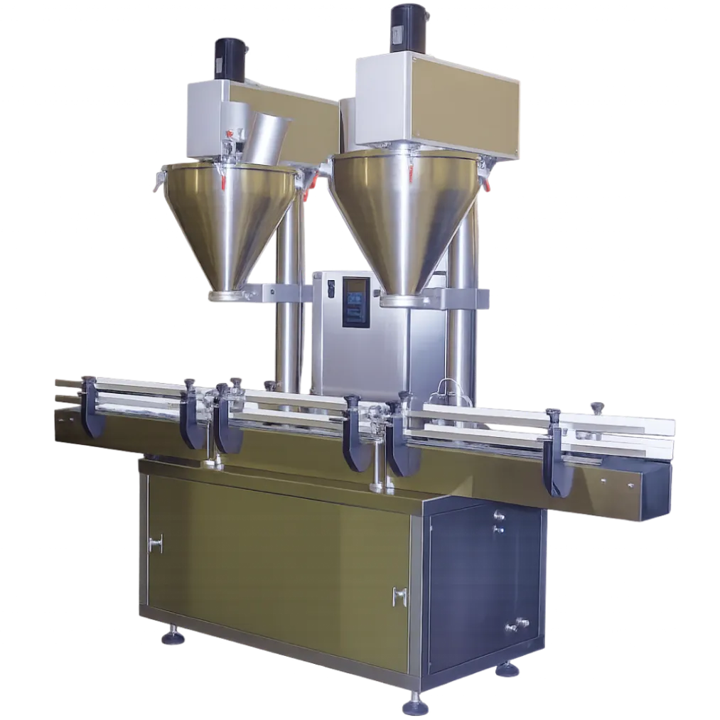
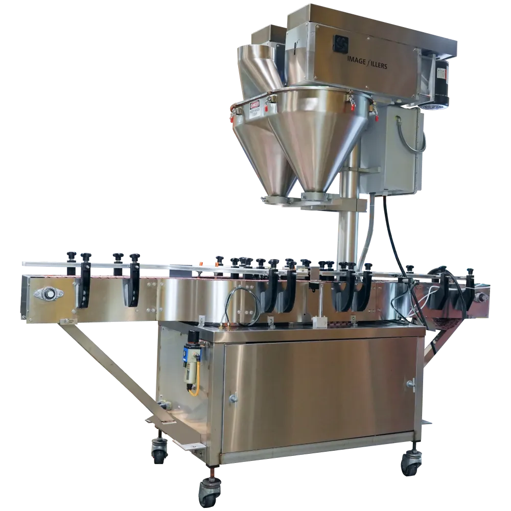
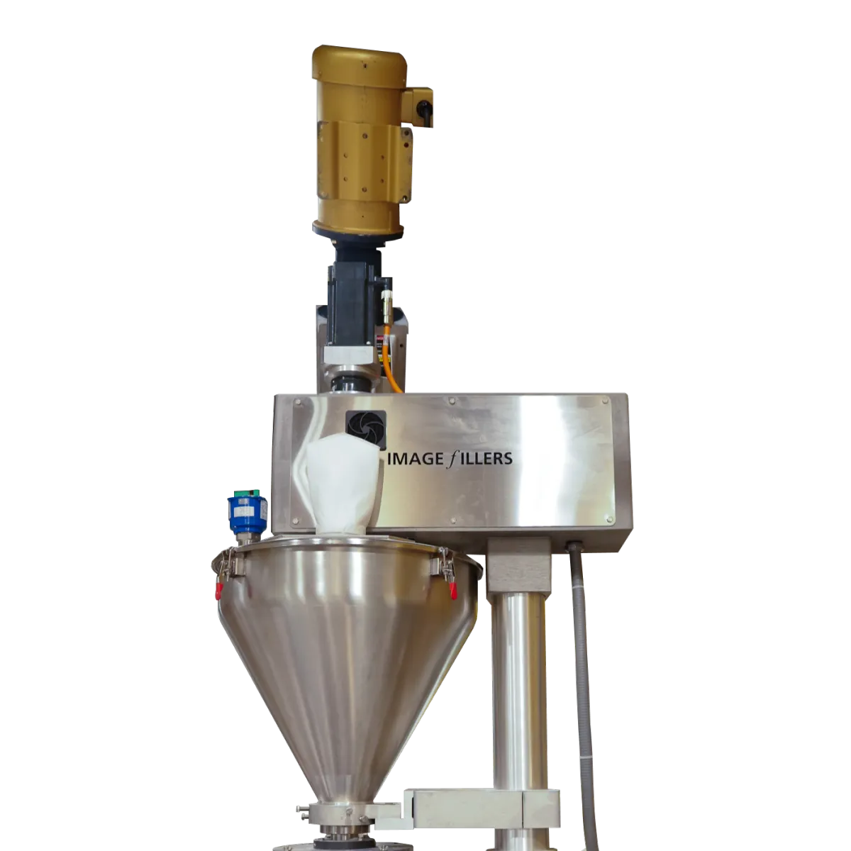
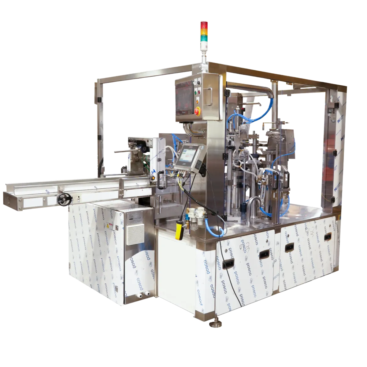
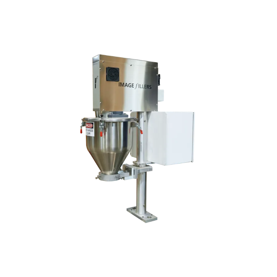
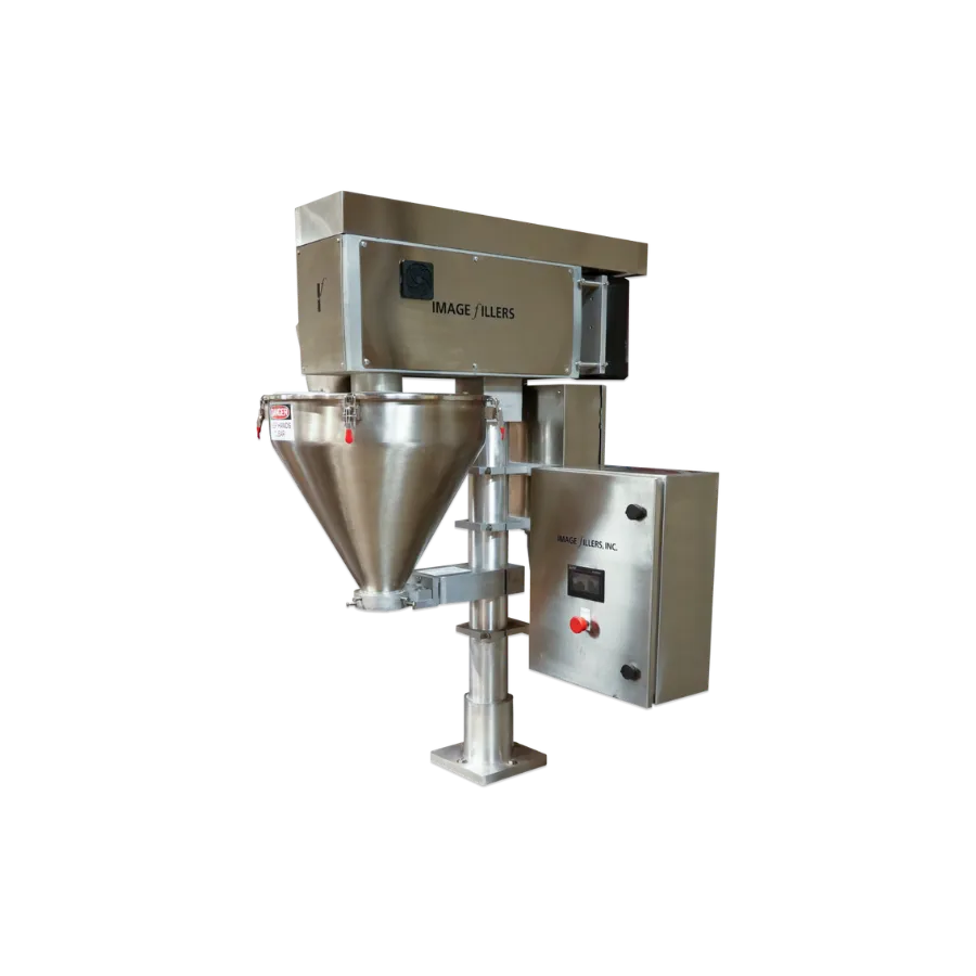
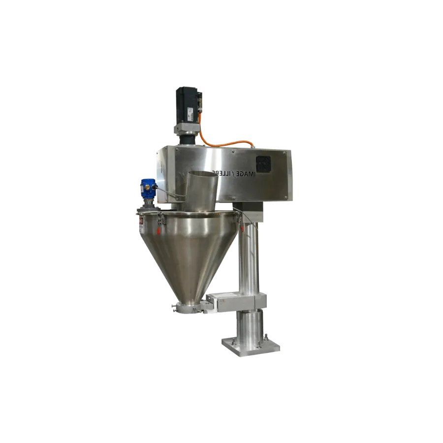
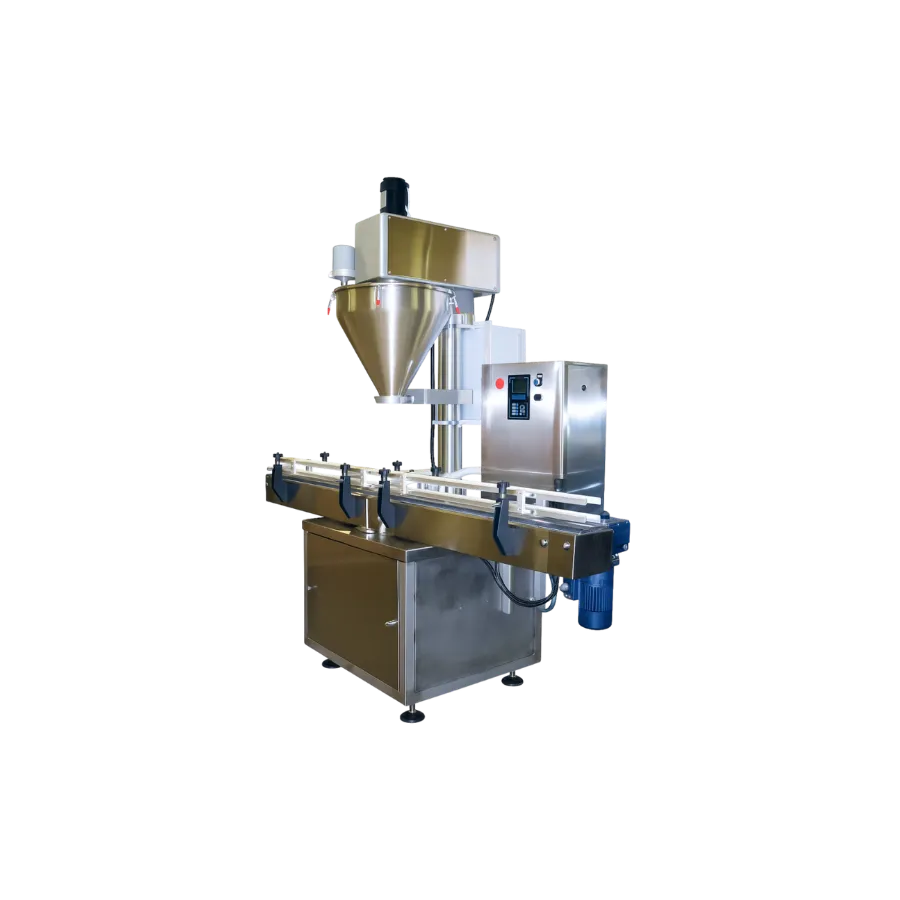
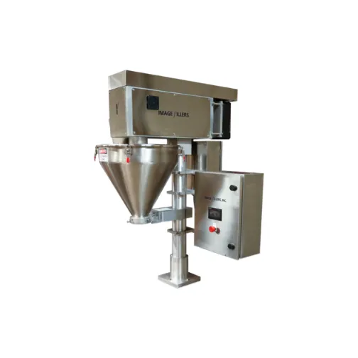
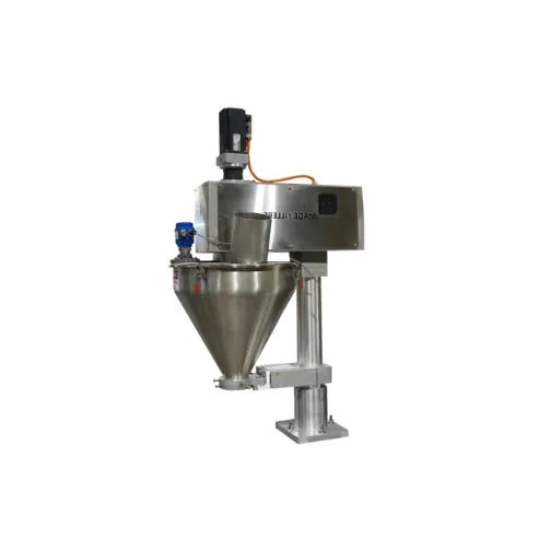
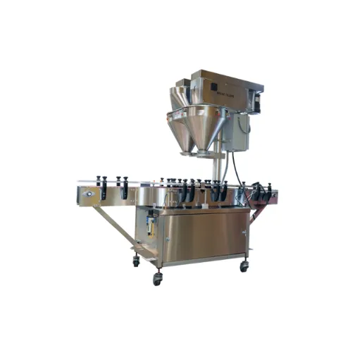
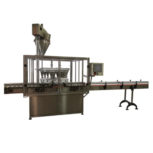
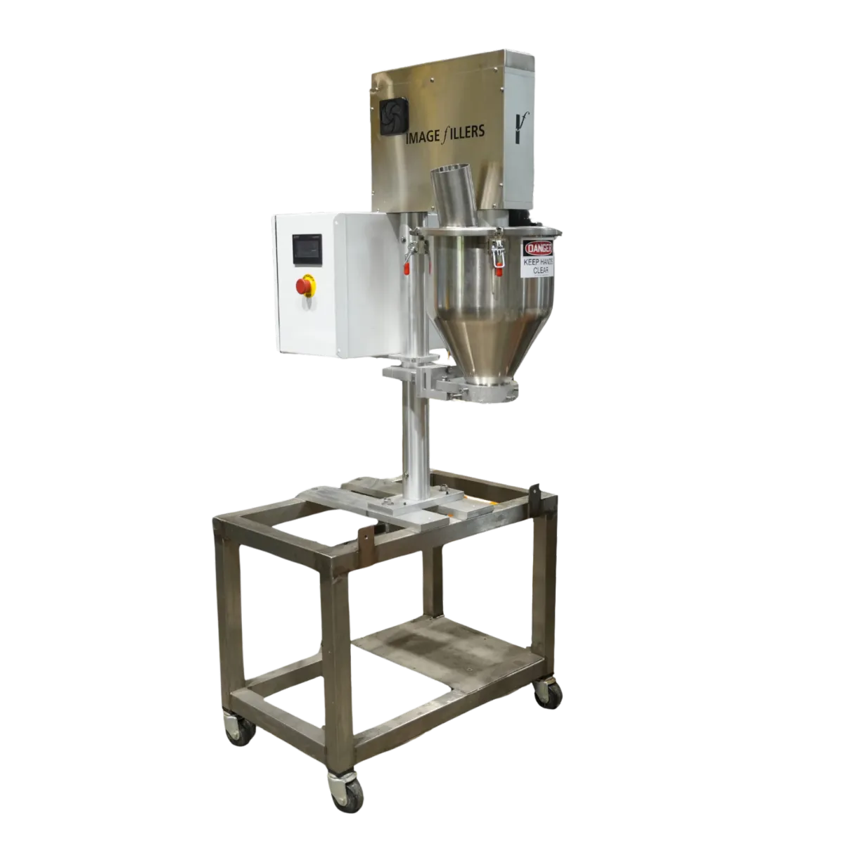
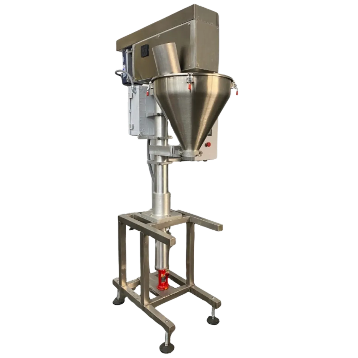
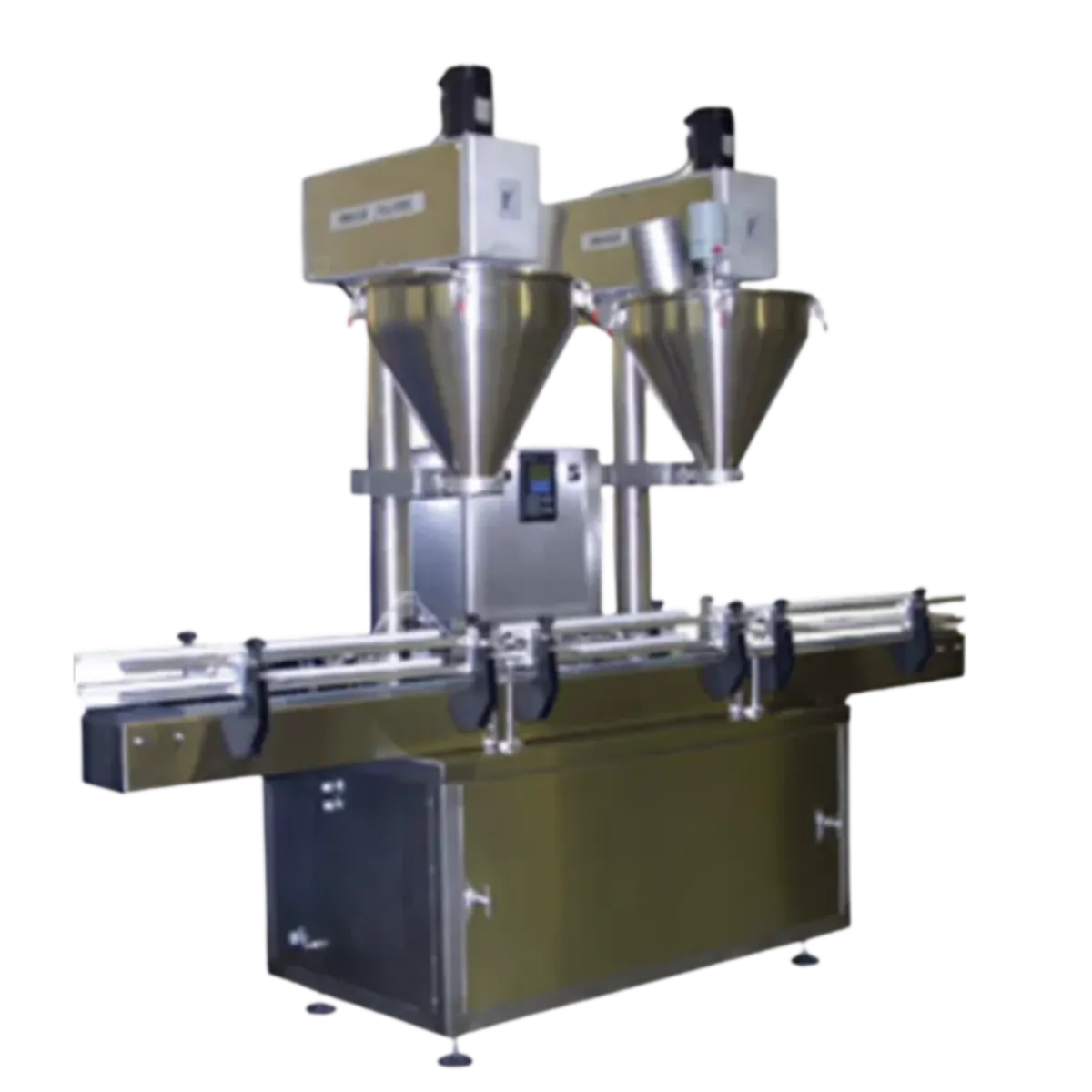
Auger Filler Machines


Contact
Hours: 9 AM - 5 PM
735 Fox Chase Rd #111, Coatesville, PA 19320
(610) 466-1440

To purchase a machine, call (610) 466-1440 or email [email protected]
Image Fillers © 2026
Made in the United States